ITO Glass – Thinner Is Better?

In recent years, the requirements for processing technology in various industries have been continuously improved. ITO (indium tin oxide) materials, for instance, have stricter criteria for line width and processing interval for ITO conductive patterns. The subject of whether the ITO laser etching machine can produce lines smaller than 20 microns comes up frequently. Is a 20-micron processing interval possible? The answer is yes. So what is the smallest line width of the ITO laser etching machine? Let SAM Sputter Target answer it for you.

What Determines the Line Width?

The laser and the optics define the thickness of the ITO line width, which is related to the size of the focus spot and the thermal impact of the source on the material. A line with a thinner width might be produced by a shorter wavelength because it has lower energy, a narrower pulse width, a higher beam expander magnification, a smaller field lens negative, and a smaller spot size. Several of the aforementioned parameters, of course, have a relative limit value. For instance, if the beam expander’s magnification is too great, the energy density will be inadequate and unsuitable for processing. As a result, we must choose a variety of values and apply them to the processing requirements.

In addition, even with the same laser etch machine, the line widths made by different materials are different. For example, the etch line width of a nickel alloy material is thicker than that of an ITO material, depending on the absorption of the laser wavelength by the material itself. This article analyzes based on ITO conductive glass.
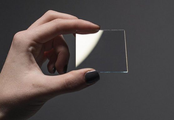
ITO glass

Thickness Requirements of Different Industries

The general requirement for ITO glass in the touch screen industry is less than 20 microns, which uses a narrow pulse-width infrared nanosecond laser. Different industries have different requirements for ITO line width. In some industries, the resistance of ITO line width has relatively high requirements, while in some industries, it is required to ensure that it is cut and insulated. In the current laser market, the minimum line width of ITO conductive glass is 5 micrometers, and different line widths can be selectively selected according to different light sources. For example, the minimum line width of an ultraviolet nanosecond laser can be 15 micrometers. Of course, there are also EUV lithography machines that can achieve nanometer levels by means of extreme ultraviolet lasers. The requirements for line width are mainly determined by different product requirements.

Thinner is Better?

From the above, you can see that different industries have different thickness requirements for ITO glass. What is certain is that the thinner is not always the better. It still needs to be designed and manufactured according to the specific application.

Differences Between CVD and PVD Processes and Technologies

The most popular surface treatment technologies, chemical vapor deposition (CVD) and physical vapor deposition (PVD), have been used extensively for nearly 50 years to harden the surfaces of tools and molds. The context that follows compares the technologies and processes of CVD and PVD using the illustration of cutting tools.


Rationale

In the process known as chemical vapor deposition (CVD), a vapor containing a gaseous reactant or a liquid reactant that makes up a thin film element as well as other gases necessary for the reaction are introduced into a reaction chamber in order to chemically react on the surface of the substrate to form a thin film.

Physical vapor deposition (PVD) uses low-voltage, high-current arc discharge technology under vacuum conditions to evaporate the target and ionize the vaporized material and the gas, and finally make the evaporated material and its reaction deposited on the workpiece.


Image Credit: Stanford Advanced Materials

Process and Equipment

1. Temperature

The fundamental distinction between CVD and PVD is temperature. The tools must undergo a vacuum heat treatment after coating since the process temperature of the CVD method is higher than the high-speed steel’s tempering temperature. This will restore the tools’ hardness.

2. Compared to PVD, the CVD method requires less cleaning of the tool entering the reactor.

3. The PVD coating (approximately 2.5 m) is thinner than the CVD coating (about 7.5 m) on the tool’s surface.

4. The CVD coating’s surface is marginally rougher than the substrate’s surface. On the other hand, the PVD coating has a good metallic sheen without grinding and effectively reflects the tool’s surface.

5. The crafting process

CVD has good coating performance and takes place in a gaseous atmosphere with low vacuum. Hence, every surface of the cutters encased in the reactor, including deep holes and inner walls, can be entirely coated, with the exception of the support points.

In contrast, all PVD technologies have poor coating performance both on the back and sides of the tool due to low air pressure. To prevent the production of shadows, the PVD reactor must minimize its loading density, and loading and fixing are challenging. In a PVD reactor, the tool typically revolves constantly, though occasionally it must also reciprocate.

6. Cost

Although the PVD production cycle is one-tenth that of CVD, the initial equipment expenditure is three to four times that of CVD. Whereas PVD is severely constrained, a wide range of workpieces can be treated within a CVD operating cycle. In other words, PVD can cost more than CVD in some cases.

7. Safety

As a form of “green engineering,” PVD creates less pollution when operating. Contrarily, the reactive gas and reaction tail gas of CVD may have some corrosiveness, flammability, and toxicity, and the reaction tail gas may contain powdered and fragmented chemicals, thus particular precautions for the equipment, environment, and operators must be taken.


Stanford Advanced Materials supplies high-quality and consistent products to meet our customers’ R&D and production needs. You can visit our website for more information.